Biotracer Applet
This tutorial covers the steps needed to giving HUGIN model a user friendly interface and deploying it online.
The Biotracer Demo project is based on a Server / Client architecture. The client side is an Applet that can be initialized either from the Hugin GUI tool or any web browser (IE, Firefox etc.). There are many security restrictions on applets that run on browsers (No access to the local file system, cannot display popup warning messages, etc.). The Hugin applet needs access to the local file system so in order to get around some security restrictions the applet has been digitally signed.
This requires the user to trust the applet before it is initialized in a browser. Figure 1 shows the digital signature that appears when loading the applet in Internet Explorer. The user needs to press the Run button in order to trust the applet.
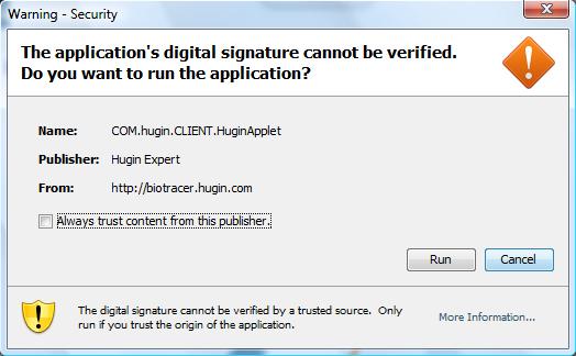
Figure 1: Digital signature for trusting the Biotracer Applet
If the user chooses not to trust the applet, many features will not function correctly (No access to the local file system, connection to a third party database will not be possible, etc.).
When the applet is trusted, the user obtains access to the Biotracer system with all its functionality enabled. This document is a guide for using the applet to perform various tasks.
Login
When the applet is initialized, the first panel displayed to the user is the Log In panel (Figure 2) for authenticating the user. Type in the username and the password provided by the administrator and press the OK button to log in.
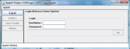
Figure 2: Log in panel
There are three different types of users in the Biotracer system, each with different rights.
Read: This type of user can only view information in the applet.
Read Write: Can view information, upload / remove data, connect to a database.
Administrator: This type of user has all rights including managing users (adding / removing users and changing user rights) and scheduling database dumps.
After typing in the login information the user should press the OK button to get access to the system.
File System
After logging in the Biotracer system the Applet looks like in Figure 3. To the left of the panel, there are four buttons that navigate the user in the Biotracer Demo system. The right side of the applet shows the Folders panel as it would look like when selecting the Folders button.
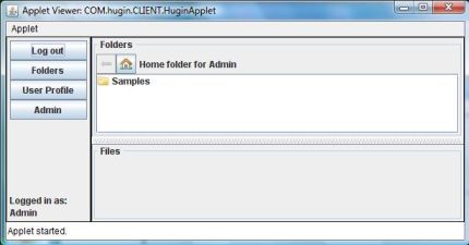
Figure 3: The Biotracer Appletafter logging in
The Folders panel displays a list of folders and files in the selected folder. Currently the Biotracer System supports two kinds of files. The .net files that represent Hugin models and .dat files that represent Hugin case files. Double clicking on the Samples (Figure 3) folder opens the folder and displays its content. Figure 4 shows the content of the Samples folder.
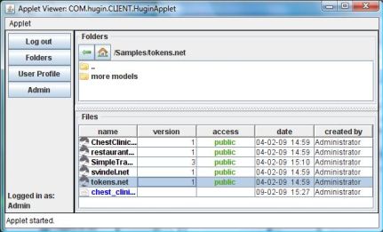
Figure 4: The Folder Panel showing the contents if the Sample folders
The top part of the panel displays the folders contained in the Samples directory. Selecting a folder and then right clicking on the mouse will display a popup menu that allows the user to create a new folder, or rename and delete an existing one (Figure 5).

Figure 5: Folder popup displayed when right clicking on a folder
The bottom part of the Folders panel (Figure 4) shows a list of all the files included in the Samples folder. A large part of the functionalities in the Biotracer Demo system is located her. By selecting a file and right clicking on the mouse a popup menu appears offering the user various options.
Figure 6 shows the popup menu for a Hugin model file. A description of every option in this menu is described below.
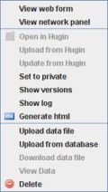
Figure 6: Popup menu for Hugin model files
View web form
Pressing the View web form option displays the web form for the selected model. Figure 7 shows the web form for the model ChestClinic.net. This can also be achieved by double clicking on a Hugin model file. The web form allows the user to make observations on the model after entering evidence and it is designed in the Hugin GUI tool and saved in the model file.
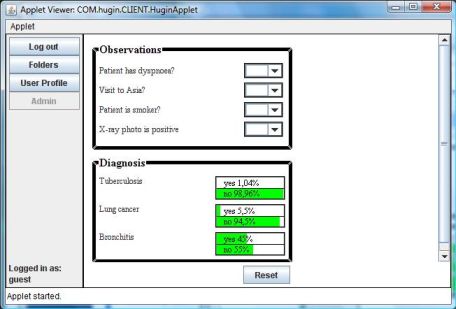
Figure 7: Web form for the ChestClinic.net model
View network panel
Selecting this option will display the graphical structure of the selected Hugin model as it is shown in the Hugin GUI tool, see Figure 8.
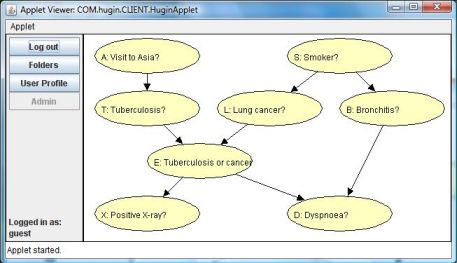
Figure 8: Network panel showing the ChestClinic.net model
The network panel allows the user to get an overview of the structure of the selected Hugin model to better understand the relations between nodes.
Open in Hugin
This option opens the selected Hugin model in the Hugin GUI tool. In order to be able to select this option the Biotracer Demo applet should be initialized from within the Hugin GUI tool.
Upload from Hugin
This is only available when initializing the applet from the Hugin GUI tool. Selecting this option displays a dialog that allows the user to select a model currently opened in the Hugin tool and upload it to the server (Figure 9).
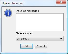
Figure 9: Panel that allows the user to upload a model
The Biotracer Demo system supports versioning of Hugin models uploaded to the server. Each version has a log message attached. The top part of the dialog (Figure 9) allows the user to input the initial log message for the newly uploaded model. The system saves the model in a database and registers the model name, the version number, the access value, the date and the name of the person that uploaded it.
Update from Hugin
Changes on a model can only be done by using the Hugin GUI tool. If these changes should be applied to the model residing on the server, the Update from Hugin option should be selected after selecting the desired model in the applet. A Dialog similar to the one when uploading a new model (Figure 9) appears and the user can again select the correct model opened in Hugin, write a log message describing the changes made on the model and upload the model to the server. The Biotracer System creates a new version of the model and registers the name of the model, the log message, the date the model was changed and the name of the user that made the changes. If the name of the model selected does not match the name of the model on the server, a message appears warning the user that he might have selected the wrong model.
Set to private / Set to public
The Hugin models saved on the server can be used for demonstration purposes on various websites (see Generate html). The access attribute specifies if a model should be public or private. A public model can be used in any website but a private model can only be accessible through this applet after user authentication.
Show versions
If the selected model has more that one version, this option displays all its versions in the file list and gives the user the ability to view each versions web form and network panel.
Show log
Selecting the Show log option displays the log panel that contains a list of the different versions of the selected model (Figure 10). When selecting a version, the log message is displayed at the bottom area of the log panel.
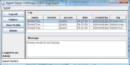
Figure 10: The log pannel shows all version of a model and their log date
Pressing the Folders button on the left side of the applet returns to the folder panel for the last visited folder.
Generate html
The web form and the network panel of a model saved in the Biotracer Demo system can be loaded in a web browser directly without requiring user authentication. The only requirement for this to be possible is that the model is public (see Set to private / Set to public). Choosing the Generate html option generates a file with the html code needed to load applets with a web form and a network panel, see Figure 11. The loaded applets are not digitally signed as they do not need to access the local file system or do any other tasks that require overcoming the security limits.
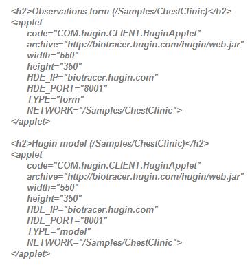
Figure 11: Generated html coode for loading a web form applet and a network panel applet for "ChestClinic"
The first block of html code imports an applet with the web form for the ChestClinic model and the second one imports the network panel. The only difference between the two code blocks is the type attribute. The size of the applets can be adjusted by changing the values of the width and height attributes.
The first block of html code imports an applet with the web form for the ChestClinic model and the second one imports the network panel. The only difference between the two code blocks is the type attribute. The size of the applets can be adjusted by changing the values of the width and height attributes.
Upload data file
A data file is a comma separated file that contains cases for a model. The Upload data file option allows the user to upload a data file from the clients local file system to the server.
Upload from database
The Upload from database option loads the Database Panel (Figure 12) in the applet. Here the user can connect to a database, view the content of tables and views and generate a case file for a particular model in the system. The connection to a database is achieved through Java Database Connectivity (JDBC) drivers provided by the user. A database URL is a Universal Resource Locator (URL) that specifies a particular type of database server (compatible with the local JDBC driver) and a particular host. To connect to a database using the Database panel, insert the URL, the user name and the password provided by the database administrator. Press the Driver button to select the .jar file containing the JDBC driver. Some databases require a licence jar file to allow a connection. In that case make sure the licence file is located in the same folder as the driver jar file. Press the Connect button to connect.
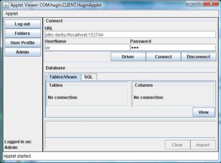
Figure 12: The database panel connects to databases through their JDBC driver
If everything is done correctly, a connection is established and a list of all tables and view is displayed in the middle of the database panel. Selecting a table/view will show all its columns to the right of the table list. Pressing the View button will display the content of the selected table, see Figure 13.
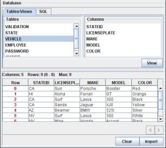
Figure 13: Displaying the columns and the content of the "vehicle" table
In most cases the user will need to extract data from more than one table and change the names of the columns so they match the node names in a model. This can be achieved by using SQL statements. SQL statements can be entered and executed in the SQL editor that is available by selecting the SQL tab (Figure 14). Only select statements can be executed in this editor.
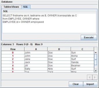
Figure 14: Results generated by executing an SQL statement
The database used in this example has nothing to do with any models in the Biotracer system; it is just used for demonstrating database connectivity and data extraction. After executing the select statement (by pressing the Execute button) a table is displayed at the bottom of the applet with the results. The generated data can be imported in the Biotracer system as a .dat file by pressing the Import button. A window appears prompting the user to type in the name of the new file and the file is saved in the last visited folder (Figure 15).
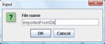
Figure 15: Window for typing in a new file
It is good practice to disconnect from the database when finished extracting data, otherwise the database connection is closed when the applet is destroyed. Pressing the Folders button on the left side of the applet returns to the last visited folder.
Download data file
This option downloads the selected data file to the clients local file system.
View Data
When selecting the View Data option the Data viewer (Figure 16) is displayed in the applet; this allows the user to view the contents of the selected data file. The default separator is ,. Pressing the view button shows a table with the contents of the file.
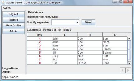
Figure 16: Viewing the content of a data file
Pressing the Folders button returns back to the last visited folder.
User Profile
Every user regardless of their rights in the system can change his own profile information by pressing the User Profile button.
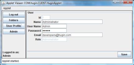
Figure 17: A panel for editing the user profile
A panel is displayed (Figure 17) allowing the user to change all information except the user id and his role in the system. User ids are generated by the system and user roles can only be changed by the administrator.
Administration
The administration tasks are enabled only for a user that is logged in as administrator. Pressing the Admin button displays a tabbed panel offering the user the means for administrating users and the system database.
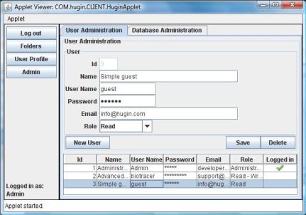
Figure 18: A panel for administrating the system users
The User Administration tab (Figure 18) displays all the users in the Biotracer Demo database and allows the administrator to create, edit and delete users. There should be minimum one user with the administrator role.
The Database Administrator tab (Figure 19) initializes a panel for scheduling and creating a database dump and restoring the database from a dump. A dump is a folder containing information about the structure of the database and the data stored. It is created on the server so the administrator can restore the database in case of failure or restructure.
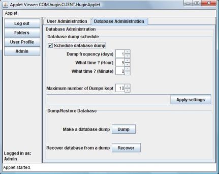
Figure 19: The system database administration panel
On the top of the panel the user can schedule automatic dumping of the database by selecting the Schedule database dump check box. The Dump frequency box specifies the number of days between database dumps, the Hour box specifies the hour of the day and the Minute box specifies the minute of the hour. To avoid filling up the server with an unlimited number of dump folders, the system keeps only the most current dumps. The limit of stored dumps is defined in the Maximum number of dumps box. After changes are made to the schedule setting, the Apply settings button should be pressed to save. A dump can also be created manually by pressing the Dump button. To restore the database the user should press the Recover button to select the desired dump folder (Figure 20) to be used for structuring and populating the database.
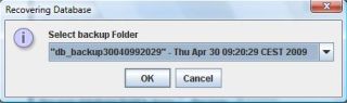
Figure 20: A panel for selecting a database dump stored on the server
The most recent folder is located at the bottom of the drop down box.